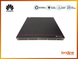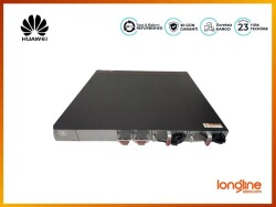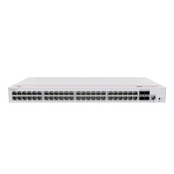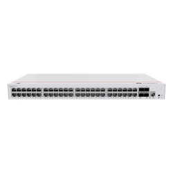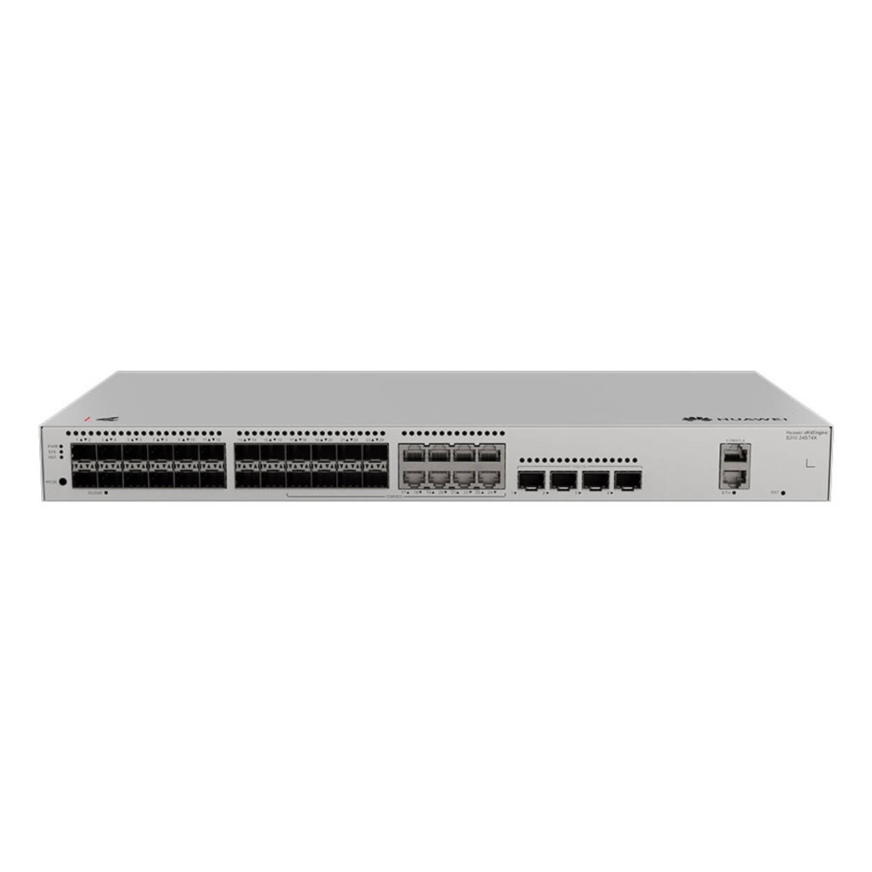
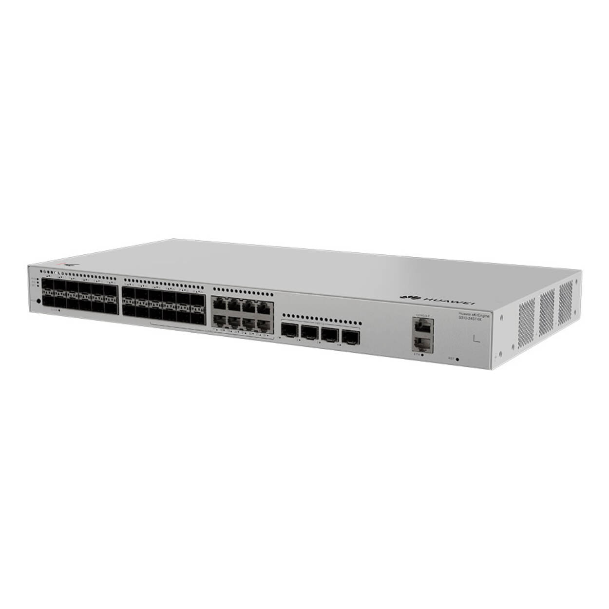
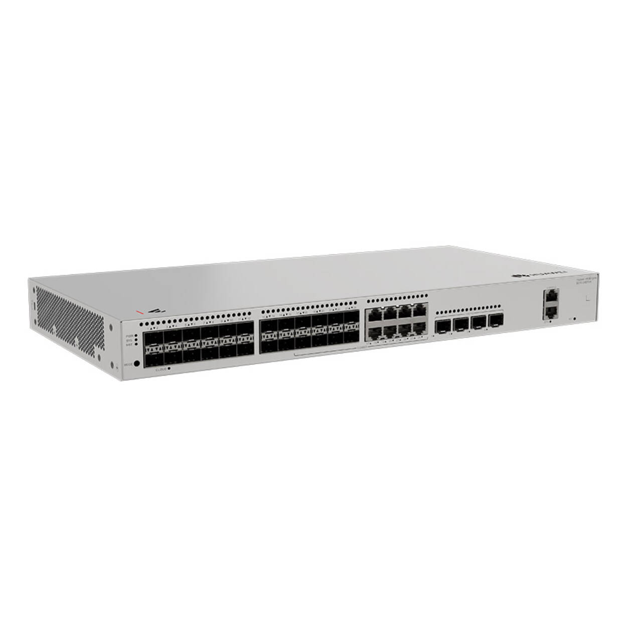
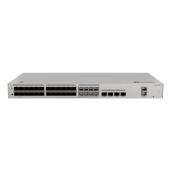
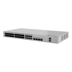
S310-24ST4X(24*GE SFP ports, 8 of which are dual-purpose 10/100/1000 or SFP, 4*10GE SFP+ ports, built-in AC power)
| Item | Details |
|---|---|
| Description | S310-24ST4X(24*GE SFP ports, 8 of which are dual-purpose 10/100/1000 or SFP, 4*10GE SFP+ ports, built-in AC power) |
| Part Number | 98012532 |
| Model | S310-24ST4X |
| First supported version | V600R023C10SPC600 |

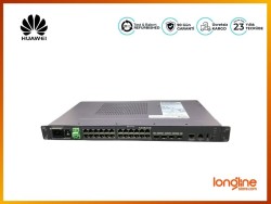
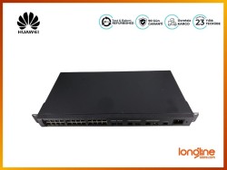
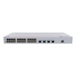
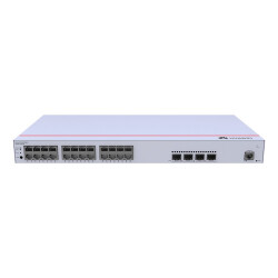
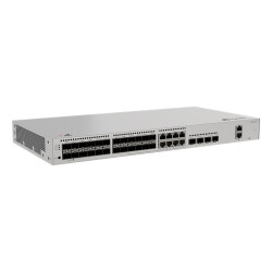
1 | One MODE button | 2 | Sixteen 100/1000BASE-X ports |
3 | Eight Combo ports (100/1000BASE-X optical ports and 10/100/1000BASE-T electrical ports) NOTE: In the default working mode, the electrical ports in the combo ports are available. | 4 | Four 10GE SFP+ ports |
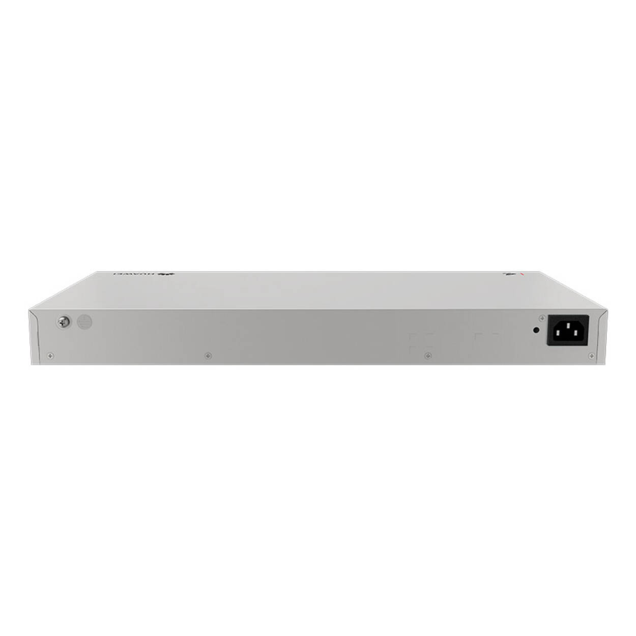
5 | One console port | 6 | One ETH management port |
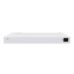
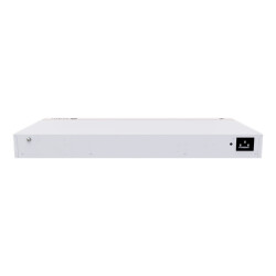
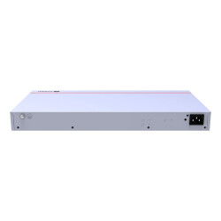
7 | One RST button NOTICE: To restore the factory settings and reset the device, hold down the button for at least 6 seconds. To reset the device, press the button. Resetting the device will cause service interruption. Exercise caution when you press the button. | 8 | Ground screw NOTE: It is used with a ground cable. |
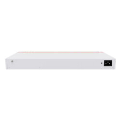
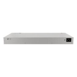
9 | Jack for AC power cable locking strap NOTE: The AC power cable locking strap is not delivered with the switch. | 10 | AC socket NOTE: It is used with an AC power cable. |
| Port | Connector Type | Description | Available Components |
|---|---|---|---|
| 100/1000BASE-X port | SFP | A 100/1000BASE-X port can send and receive data at 100/1000 Mbit/s. | |
| Combo port (10/100/1000BASE-T + 100/1000BASE-X) | RJ45/SFP | A combo port refers to a pair of ports consisting of an optical Ethernet port and an electrical Ethernet port on the panel. Each combo port matches only one internal forwarding port. A combo port can be configured as an electrical port or an optical port, but only one port can be active at a time. When one port is active, the other port is shut down. | |
| 10GE SFP+ optical port | SFP+ | A 10GE SFP+ Ethernet optical port supports auto-sensing to 1000 Mbit/s. It sends and receives service data at 1000 Mbit/s or 10 Gbit/s. |
|
| Console port | RJ45 | The console port is connected to a console for on-site configuration. | |
| ETH management port | RJ45 | You can connect a switch to a configuration terminal or network management workstation through the ETH management port to configure the switch locally or remotely. |

No. | Indicator | Name | Color | Status | Description |
|---|---|---|---|---|---|
1 | PWR | Power module indicator | - | Off | The switch is powered off. |
Green | Steady on | The power supply is normal. | |||
2 | SYS | System status indicator | - | Off | The system is not running. |
Green | Fast blinking | The system is starting. | |||
Green | Steady on | During the system startup preparation phase, the SYS indicator is steady green, which lasts for a maximum of 30 seconds. | |||
Green | Slow blinking | The system is running normally. | |||
Red | Steady on | The system does not work normally after registration, or a fan alarm or a temperature alarm has been generated. | |||
3 | MST | Stack indicator | - | Off |
|
Green | Steady on | The stack mode is selected. The switch is a standby or slave switch in a stack, and the service port indicators show the stack ID of the switch. | |||
Green | Blinking |
| |||
4 | MODE | Mode switch button | - | - |
If you do not press the MODE button within 45 seconds, the service port indicators restore to the default mode. NOTE: Hold down the mode switch button for 6s and release it to start the web initial login mode. Either of the following situations will occur:
|
5 | CLOUD | Cloud indicator NOTE: In versions earlier than V600R024C00, this indicator is reserved. | - | Off | The device is not in the cloud management state. |
Blue | Fast blinking | The device is connecting to the cloud. | |||
Blue | Slow blinking | The device is in the cloud management state. | |||
Blue | Steady on | The network is connected, and the management VLAN of the device obtains an IP address. | |||
6 | - | Optical service port indicator (two indicators for each port) | Each optical port has two single-color indicators. The one on the left is the ACT indicator (yellow), and the one on the right is the LINK indicator (green). Arrowheads show the positions of ports. A down arrowhead indicates a port at the bottom, and an up arrowhead indicates a port at the top. | Meanings of service port indicators vary in different modes. For details, see Table 4-104 and Table 4-105. NOTE: If a power failure occurs on a device's PCB board, indicators of the last four GE or 10GE optical ports on the device's front panel blink green cyclically at an interval of 1 second, with each indicator illuminating for 0.25 seconds. | |
7 | - | Electrical or optical service port indicator (one indicator for each port) | Arrowheads show the positions of ports. A down arrowhead indicates a port at the bottom, and an up arrowhead indicates a port at the top. | ||
8 | ETH | ETH port indicator | - | Off | The ETH port is not connected. |
Green | Steady on | The ETH port is connected. | |||
Green | Blinking | The ETH port is sending or receiving data. | |||
Display Mode | Color | Status | Description |
|---|---|---|---|
Default mode | - | Off | The port is not connected or has been shut down. |
Green | Steady on | A link has been established on the port. | |
Green | Blinking | The port is sending or receiving data. |
Display Mode | Color | Status | Description |
|---|---|---|---|
Default mode (LINK indicator) | - | Off | The port is not connected or has been shut down. |
Green | Steady on | A link has been established on the port. | |
Default mode (ACT indicator) | - | Off | The port is not connected or has been shut down, or no data is transmitted or received. |
Yellow | Blinking | The port is sending or receiving data. | |
MST stack mode (LINK indicator) | - | Off | Port indicators do not show the stack ID of the switch. |
Green | Steady on | The switch is not the master switch in a stack. If the indicator of a port is steady on, the number of this port is the stack ID of the switch. | |
Green | Blinking | The switch is the master switch in a stack. If the indicator of a port is blinking, the number of this port is the stack ID of the switch. | |
MST stack mode (ACT indicator) | - | Off | Port indicators do not show the stack ID of the switch. |
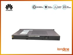
The switch has a built-in AC power module and does not support pluggable power modules.
The switch has two built-in fans for forced air cooling. Air flows in from the left side and front panel, and exhausts from the right side.
When working properly at a normal temperature, the device meets the desktop-class noise requirements. However, the fan speed may be high and the noise may be loud during device startup.

This figure only shows the airflow direction and does not depict the actual device.
| Item | Specification |
|---|---|
| Dimensions without packaging (H x W x D) [mm(in.)] | Basic dimensions (excluding the parts protruding from the body): 43.6 mm x 442.0 mm x 220.0 mm (1.72 in. x 17.4 in. x 8.66 in.) Maximum dimensions (the depth is the distance from ports on the front panel to the parts protruding from the rear panel): 43.6 mm x 442.0 mm x 227.0 mm (1.72 in. x 17.4 in. x 8.94 in.) |
| Dimensions with packaging (H x W x D) [mm(in.)] | 90.0 mm x 550.0 mm x 360.0 mm (3.54 in. x 21.65 in. x 14.17 in.) |
| Chassis height [U] | 1 U |
| Weight without packaging [kg(lb)] | 2.9 kg (6.39 lb) |
| Weight with packaging [kg(lb)] | 3.55 kg (7.83 lb) |
| Typical power consumption [W] | 32.6 W |
| Typical heat dissipation [BTU/hour] | 111.23 BTU/hour |
| Maximum power consumption [W] | 41.7 W |
| Maximum heat dissipation [BTU/hour] | 142.28 BTU/hour |
| Static power consumption | 17.57 |
| MTBF [years] | 47.39 years |
| MTTR [hours] | 2 hours |
| Availability | > 0.99999 |
| Noise at normal temperature (acoustic power) [dB(A)] | 38.1 dB(A) |
| Noise at normal temperature (acoustic pressure) [dB(A)] | 26.1 dB(A) |
| Number of card slots | 0 |
| Number of power slots | 0 |
| Number of fans modules | 2 |
| Switching capacity | To obtain data of this specification item, see the corresponding datasheet or contact the product sales personnel. |
| Packet forwarding rate | To obtain data of this specification item, see the corresponding datasheet or contact the product sales personnel. |
| Redundant power supply | Not supported |
| Long-term operating temperature [°C(°F)] | -5°C to +50°C (23°F to 122°F) at an altitude of 0-1800 m (0-5905.44 ft.) |
| Restriction on the operating temperature variation rate [°C(°F)] | When the altitude is 1800–5000 m (5906–16404 ft.), the highest operating temperature reduces by 1°C (1.8°F) every time the altitude increases by 220 m (722 ft.). Devices cannot start when the temperature is lower than 0°C (32°F). |
| Storage temperature [°C(°F)] | –40°C to +70°C (–40°F to +158°F) |
| Long-term operating relative humidity [RH] | 5% RH to 95% RH (non-condensing) |
| Long-term operating altitude [m(ft.)] | 0–5000 m (0–16404 ft.) |
| Storage altitude [m(ft.)] | 0-5000 m (0-16404 ft.) |
| Power supply mode | AC built-in |
| Rated input voltage [V] |
|
| Input voltage range [V] |
|
| Maximum input current [A] | 2 A |
| Memory | 2 GB |
| Flash memory | Physical space: 1 GB |
| Console port | RJ45 |
| Eth Management port | Supported |
| USB | Not supported |
| RTC | Not supported |
| RPS input | Not supported |
| Power supply surge protection [kV] | Differential mode: ±6 kV; common mode: ±6 kV |
| Ingress protection level (dustproof/waterproof) | IP20 |
| Types of fans | Built-in |
| Heat dissipation mode | Air cooling for heat dissipation, intelligent fan speed adjustment |
| Airflow direction | Air intake from left and front, air exhaustion from right |
| PoE | Not supported |
| Certification | EMC certification Safety certification Manufacturing certification |
 Kredi kartı bilgileriniz 256Bit SSL sertifikası ile korunmaktadır.